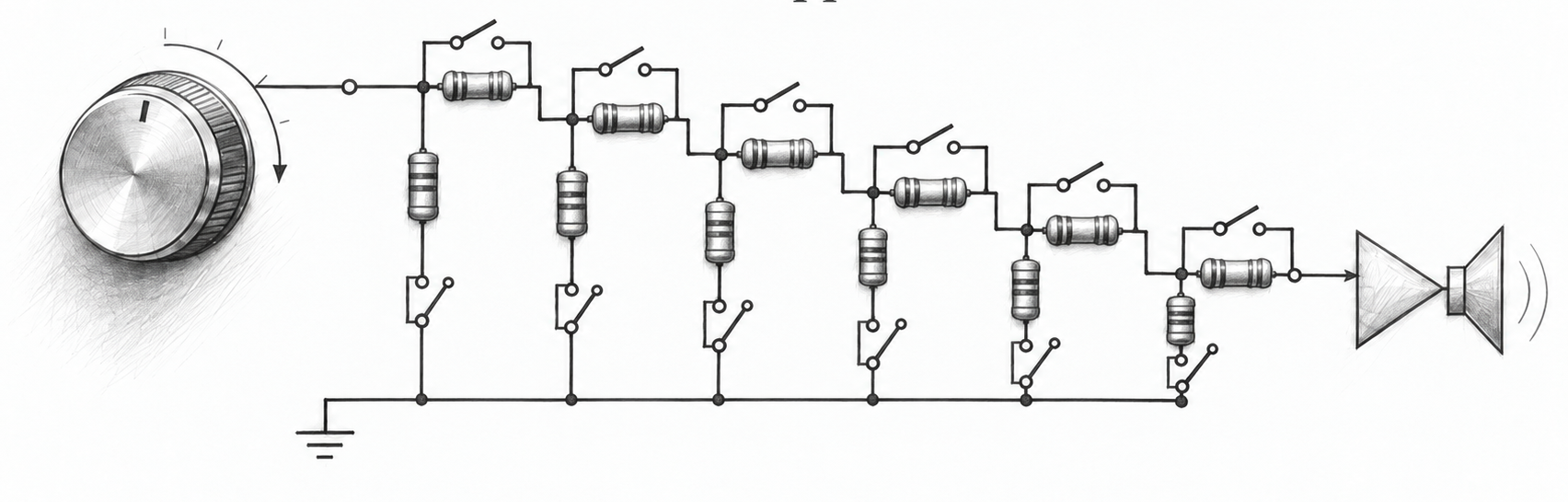
The volume knob on this amplifier is connected to a potentiometer but that isn’t anywhere near the input signal. It’s not even in the analog path. For volume control we use a switched resistor attenuator. A series of resistor stages that get inserted or shorted depending on the attenuation we need. The resistor values are chosen to create a binary construction of: 1, 2, 4, 8, 16 and 32 dB. The six-bit word N gives N dB, which is 0 to 63 dB in 1 dB steps.
Each bit is an L-pad. A series resistor R1 from the stage’s input to its output, and a shunt resistor R2 from that output to ground. Terminate the pad in Z, and let k be the voltage ratio, k = 10 to the power of minus dB over 20. Then R1 = Z(1−k) and R2 = Zk/(1−k).
Each L stage has an impedance of 10 kΩ both forwards and backwards. So as long as the next stage has an impedance of 10 kΩ, we can add and insert as we wish without changing the impedance see by the input source, or by the output load.
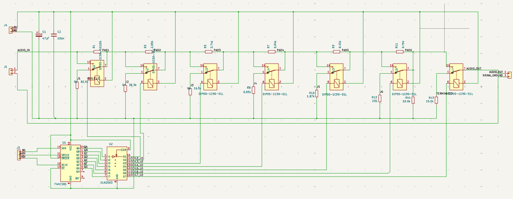
If you look at the schematic you’ll see a clever trick with the NC-NO relays (not my idea). Each relay controls two resistors with a single switch. It shorts (or doesn’t) the series resistor AND it connects (or disconnects) the ground resistor. Look at R1 and R2 for example.
Controlled relay noise: the mute
When changing attenuation, the relays that encode the new value may not switch on and off at exactly the same time, an in particular transitions from 011111 to 100000 may introduce short attenuation spikes. To get around this, we have a parallel mute circuit, a 10 kΩ resistor that grounds the output. Before changing a attenuation setting, we switch the output to mute. We do our attenuation changes and then switch back from mute to attenuation. This is relatively fast, less than 10 ms, perhaps even 5 ms. Either way, this is too short for the listener to notice.
A microcontroller manages the sequence, including allowance for relay bouncing. This is all theory of course, we will see whether turning the attenuator knob gives a smooth sound experience. Wait, what attenuator knob? Ideally, I would install an opto encoder shaft but for the first prototype I’m using a potentiometer. An onboard controller ADC reads the potentiometer, calculates the corresponding attenuator settings, determines the steps to take and manages the change sequence.
The controller communicates with the attenuator via 74C595 shift register, shifting in the 6 bits for the attenuator setting, 1 for the mute and 1 unused position. Once the bits are shifted via in SER at the pace of the SRCLK clock signal, the RCLK copies the byte to the output register. This is then boosted by the ULN2003 that drives the relays. The ULN2003 also has diodes from the output to the +5V to limit reverse voltage spikes from the relay coils when they switch off.
Does it work?
The board is at the fab now and the parts are on order. It’s the first Phoph board I’m building. Why this one? Because the whole attenuator and controller setup is fun. It’s a bit of software, digital components and a pure analog attenuator chain. It’s also the board that gets closest to a high end amplifier topology. No gold plate relay contacts yet, that’s for the next iteratin of this Phoph Field.
Bench sheet — Status: at the fab
| Object | Attenuator board, one channel, 55.01 × 90.01 mm, single PCB (not stacked), 38 nets, 34 components, 132 pads |
| Function | Passive volume control. Six constant-impedance L-pads, one per bit, binary-weighted 1/2/4/8/16/32 dB; the 6-bit word N gives N dB, 0 to 63 dB in 1 dB steps, 64 states |
| Impedance | 10 kΩ nominal (Z), ruled by Henk 2026-09-12. Input impedance 10.000 to 10.049 kΩ across all 64 states (9.902 to 10.049 kΩ with the preamp’s 1 MΩ in parallel). Output impedance varies with setting, at most about Z/4 in the middle codes |
| Accuracy | 63.216 dB at full attenuation against an ideal 63.000; worst-case setting error 0.228 dB; E96 values, 1% metal film |
| Switching | Seven 1-form-C reed relays, 5 V coils, 200 Ω, 125 mW. RL1 to RL6 the bits (energised = pad out), RL7 the mute changeover: common = output, rest = R13 10.0 kΩ to audio ground, energised = ladder output. All seven released = maximum attenuation plus mute, the fail-safe direction |
| Coil budget | 7 × 25 mA = 175 mA, ≈200 mA for the +5V feed, on the 1 A auxiliary supply |
| Termination | R13 10.0 kΩ on the board (the mute terminator). R14 10.0 kΩ off the board by Henk’s ruling of 2026-09-22: the routed board does not carry it and he places it himself |
Leave a Reply