
Follow-up to the posts “Attenuator — Test Report” and “The error was never in the resistors”. Those two left one question: with the ladder’s reference finally its own, what does the whole attenuator measure?
Everything. Codes 0 to 63, one at a time, with a brief mute between states. Three oscilloscope captures at three vertical scales — 50 mV/div for the shallow codes, 5 mV/div in the middle, 1 mV/div at the bottom — stitched on overlapping plateaux. Each plateau taken as a median, with about 20 ms either side of every relay transition thrown away.
The result
| codes | fitted dB per step | RMS about the fit | worst error against ideal |
|---|---|---|---|
| 0–19 | 1.0022 | 0.050 dB | 0.113 dB |
| 20–32 | 0.9935 | 0.041 dB | 0.133 dB |
| 33–50 | 0.9853 | 0.049 dB | 0.196 dB |
| 51–63 | 0.9343 | 0.125 dB | 1.359 dB |
All 64 states are there, the staircase is monotonic, and no code is missing. Three to hold on to: **code 16 measures 15.970 dB, code 32 measures 32.022 dB, code 48 measures 47.846 dB. The same code 32 measured 27.31 dB** in October, on a board whose shunt returns shared a conductor with the relay coils.
Attenuator sweep
Using a test controller (Arduino nano), we sweep through all attenuation levels. The high attenuation at the start of the sweep is not shown as it is too low be distinguished in the graph. The reason the attenuator dips to ‘zero’ between every step is due to the short mute we do before changing the attenuation and avoid potential transients in case the bits aren’t fully in sync. These micro mutes are less than 1ms can’t be heard in the audio output of the amplifier.
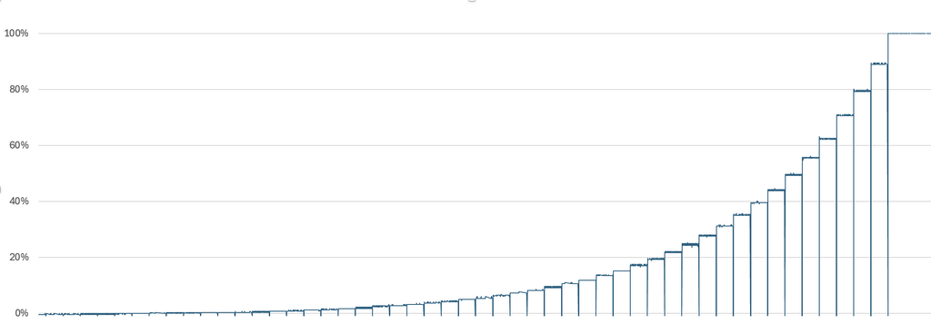
Every code
All 64 programmed states, each against the ideal 10^(−c/20): programmed attenuation, measured attenuation relative to the 0 dB plateau, and the difference. The dagger marks the codes below the measurement floor, discussed underneath.
| Code | Programmed (dB) | Measured (dB) | Error (dB) |
|---|---|---|---|
| 00 | 0.000 | 0.000 | +0.000 |
| 01 | 1.000 | 0.981 | -0.019 |
| 02 | 2.000 | 1.990 | -0.010 |
| 03 | 3.000 | 2.999 | -0.001 |
| 04 | 4.000 | 4.018 | +0.018 |
| 05 | 5.000 | 5.038 | +0.038 |
| 06 | 6.000 | 6.002 | +0.002 |
| 07 | 7.000 | 7.044 | +0.044 |
| 08 | 8.000 | 7.987 | -0.013 |
| 09 | 9.000 | 8.939 | -0.061 |
| 10 | 10.000 | 9.890 | -0.110 |
| 11 | 11.000 | 10.957 | -0.043 |
| 12 | 12.000 | 12.022 | +0.022 |
| 13 | 13.000 | 13.064 | +0.064 |
| 14 | 14.000 | 13.960 | -0.040 |
| 15 | 15.000 | 15.067 | +0.067 |
| 16 | 16.000 | 15.970 | -0.030 |
| 17 | 17.000 | 17.113 | +0.113 |
| 18 | 18.000 | 17.968 | -0.032 |
| 19 | 19.000 | 19.085 | +0.085 |
| 20 | 20.000 | 20.095 | +0.095 |
| 21 | 21.000 | 21.130 | +0.130 |
| 22 | 22.000 | 22.086 | +0.086 |
| 23 | 23.000 | 23.133 | +0.133 |
| 24 | 24.000 | 24.018 | +0.018 |
| 25 | 25.000 | 25.038 | +0.038 |
| 26 | 26.000 | 26.040 | +0.040 |
| 27 | 27.000 | 26.959 | -0.041 |
| 28 | 28.000 | 28.035 | +0.035 |
| 29 | 29.000 | 29.100 | +0.100 |
| 30 | 30.000 | 30.069 | +0.069 |
| 31 | 31.000 | 31.024 | +0.024 |
| 32 | 32.000 | 32.022 | +0.022 |
| 33 | 33.000 | 33.167 | +0.167 |
| 34 | 34.000 | 33.979 | -0.021 |
| 35 | 35.000 | 34.960 | -0.040 |
| 36 | 36.000 | 36.066 | +0.066 |
| 37 | 37.000 | 36.978 | -0.022 |
| 38 | 38.000 | 37.998 | -0.002 |
| 39 | 39.000 | 39.017 | +0.017 |
| 40 | 40.000 | 39.906 | -0.094 |
| 41 | 41.000 | 40.938 | -0.062 |
| 42 | 42.000 | 41.872 | -0.128 |
| 43 | 43.000 | 42.972 | -0.028 |
| 44 | 44.000 | 43.929 | -0.071 |
| 45 | 45.000 | 44.804 | -0.196 |
| 46 | 46.000 | 45.852 | -0.148 |
| 47 | 47.000 | 46.875 | -0.125 |
| 48 | 48.000 | 47.846 | -0.154 |
| 49 | 49.000 | 48.834 | -0.166 |
| 50 | 50.000 | 49.831 | -0.169 |
| 51 † | 51.000 | 50.565 | -0.435 |
| 52 † | 52.000 | 51.509 | -0.491 |
| 53 † | 53.000 | 52.408 | -0.592 |
| 54 † | 54.000 | 53.412 | -0.588 |
| 55 † | 55.000 | 54.347 | -0.653 |
| 56 † | 56.000 | 55.174 | -0.826 |
| 57 † | 57.000 | 56.090 | -0.910 |
| 58 † | 58.000 | 57.388 | -0.612 |
| 59 † | 59.000 | 57.968 | -1.032 |
| 60 † | 60.000 | 59.257 | -0.743 |
| 61 † | 61.000 | 59.981 | -1.019 |
| 62 † | 62.000 | 60.771 | -1.229 |
| 63 † | 63.000 | 61.641 | -1.359 |
What the bottom of the range is, and is not
Below about 50 dB the oscilloscope runs out before the attenuator does. At code 63 the wanted signal is 0.325 mV on the recorded scale, and the last plateau reads 0.380 mV. An offset of 50 to 60 µV is enough to move that reading by more than a decibel. So the last dozen codes are marked resolution-limited, not wrong — and the honest claim is the narrow one: monotonic across all 64, inside 0.2 dB to 50 dB, and not yet established below that.
If a number is ever needed at 63 dB it will not come from a scope. It wants a stable DC or low-frequency source, a high-resolution DMM, a documented zero-input offset, and both sweep directions.
You may recall we used 1% resistors in the first iteration. We then found that the measure attebnuation scale was significantly off and assumed it was due to that ‘wide’ range and ordered 0.1% resistors. We then found that wasn’t the issue, the grounds of audio path and the relay circuits had been mixed up. It was that correction – a new board – that produced the results above. I still have a set of 1% resistors and might try them out on the new board and see if they would have been adequate after all. I will update this post if they are.
Verdict
Good enough. The ladder does what it was designed to do across its whole range, the ground fault is behind it, and what is left at the bottom is a measurement question rather than a circuit one. The board measured here is that revision — shunt returns on SIGNAL_GROUND, the relay coils and their driver on their own ground — and it is the one that goes into the machine.
Measured 7 November 2026 on the new board, in which the audio path’s ground and the relay-control ground are separate conductors meeting only at the star — with a DC battery stimulus. Sources: fswp1.csv, fswp2.csv, fswp3.csv.