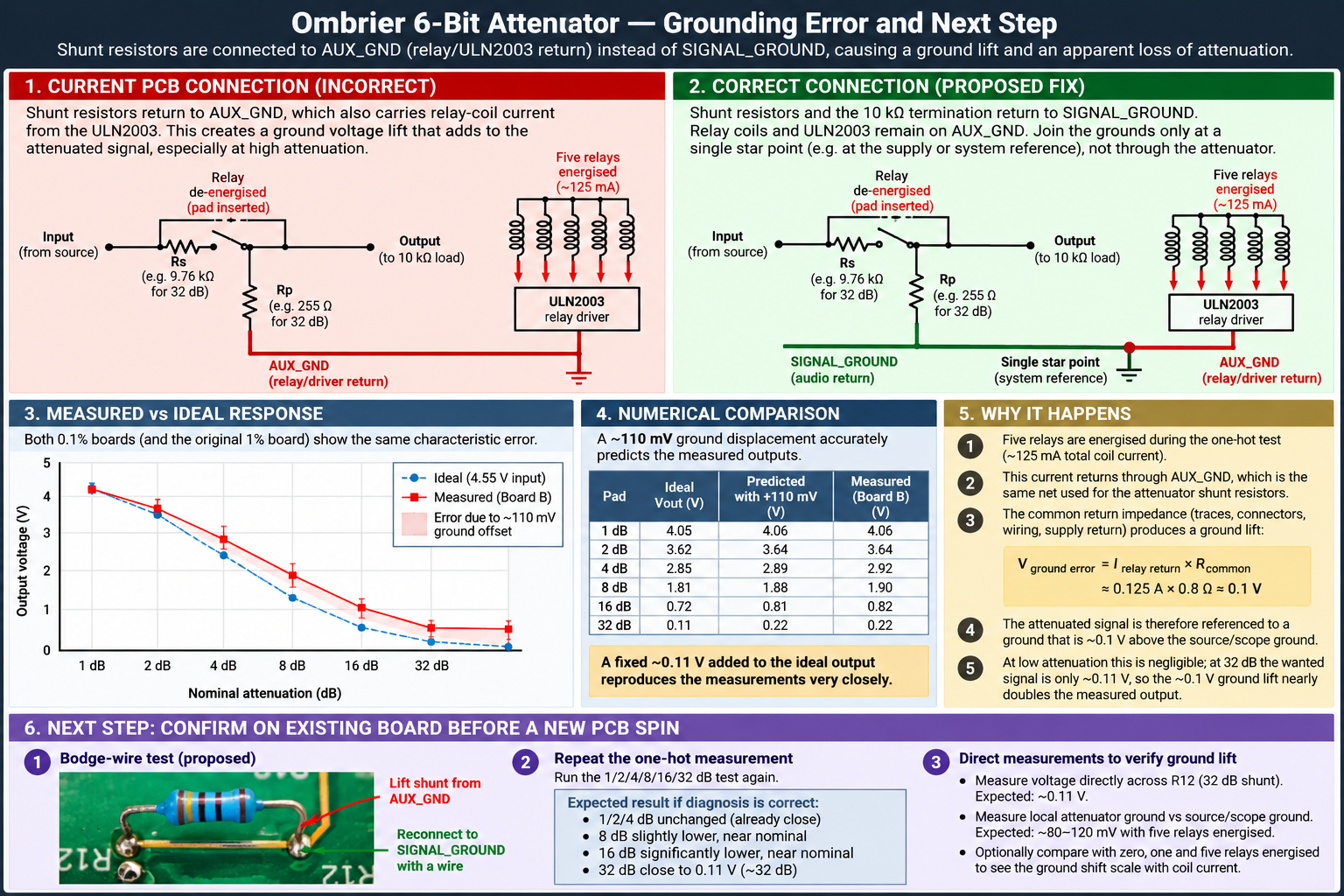
Follow-up to Attenuator — Test Report, which measured the 32 dB stage at 27.3 dB and said plainly that 1 % resistors could not account for it. The obvious next move was better resistors: two new boards, 0.1 % parts, the measurement repeated on both.
The error came back unchanged on both. It was never in the resistors.
1. One section at a time
A 64-code sweep is a bad way to look at a ladder: a binary carry changes several sections at once, and at 100 mV/div the steps near the carry boundaries look backward. So the test was changed to one-hot — one logical bit per run, five sections bypassed, one L-pad in circuit. The relay logic is inverted, so the logical word is complemented before it reaches QA–QF: 000001 is written as 111110.
| Section inserted | Board A | Board B |
|---|---|---|
| 1 dB | 3.98 V | 4.06 V |
| 2 dB | 3.56 V | 3.64 V |
| 4 dB | 2.82 V | 2.92 V |
| 8 dB | 1.84 V | 1.90 V |
| 16 dB | 0.78 V | 0.82 V |
| 32 dB | 0.22 V | 0.22 V |
Two independently assembled boards, the same staircase, the same 32 dB output to the last digit. That rules out a relay, a joint, an assembly fault and resistor tolerance. All six relays switch, and in the right order.
2. An offset, not a ratio error
The outputs do not scatter around the ideal curve. They lie on it, displaced upwards by about 0.1 V whatever the setting: V ≈ 0.975 × ideal + 0.118 V. At 4 V that is invisible. At 32 dB the wanted signal is 114 mV and the offset is as large as the signal itself — which is why the error only ever looked like a problem at the bottom of the range.
| Section | Ideal | Predicted, +110 mV | Measured, board B |
|---|---|---|---|
| 1 dB | 4.05 V | 4.06 V | 4.06 V |
| 2 dB | 3.62 V | 3.64 V | 3.64 V |
| 4 dB | 2.85 V | 2.89 V | 2.92 V |
| 8 dB | 1.81 V | 1.88 V | 1.90 V |
| 16 dB | 0.715 V | 0.807 V | 0.82 V |
| 32 dB | 0.113 V | 0.220 V | 0.22 V |
3. Where the offset comes from
The bottoms of all six shunt resistors go to /GND, the auxiliary ground — and that is the net the ULN2003 and the relay coils return through. The attenuation ratio is therefore referenced to a node carrying relay current, and any impedance in that return appears as a voltage between the reference and SIGNAL_GROUND.
The size is plausible. Five attenuation relays plus the released mute relay draw about 150 mA at 5 V and 200 Ω coils. Displacing the reference by 110 mV needs only 0.73 Ω of shared return — traces, connectors, bench wiring, common returns, counted together.
4. The correction, and the test before another board order
The audio network goes to SIGNAL_GROUND: the six shunt returns, the 10 kΩ termination, every passive part that sets the ratio. The coils, the ULN2003, the logic and its decoupling stay on AUX_GND. The two meet at the star, once.
Before ordering another PCB, prove it on a board that exists. Lift the shunt returns from /GND, wire them to SIGNAL_GROUND, leave the coils and driver alone, repeat the one-hot sweep. With 4.55 V in, 16 dB should read 0.715 V and 32 dB 0.113 V.
The lesson beyond this board: the first prototype should be an instrument, not a product — a link between the grounds that can be cut, a test point on each reference, a way to isolate a net without lifting a pad. That costs nothing on a development board and saves a fabrication cycle when an assumption turns out to be wrong, which on a first board it usually is.