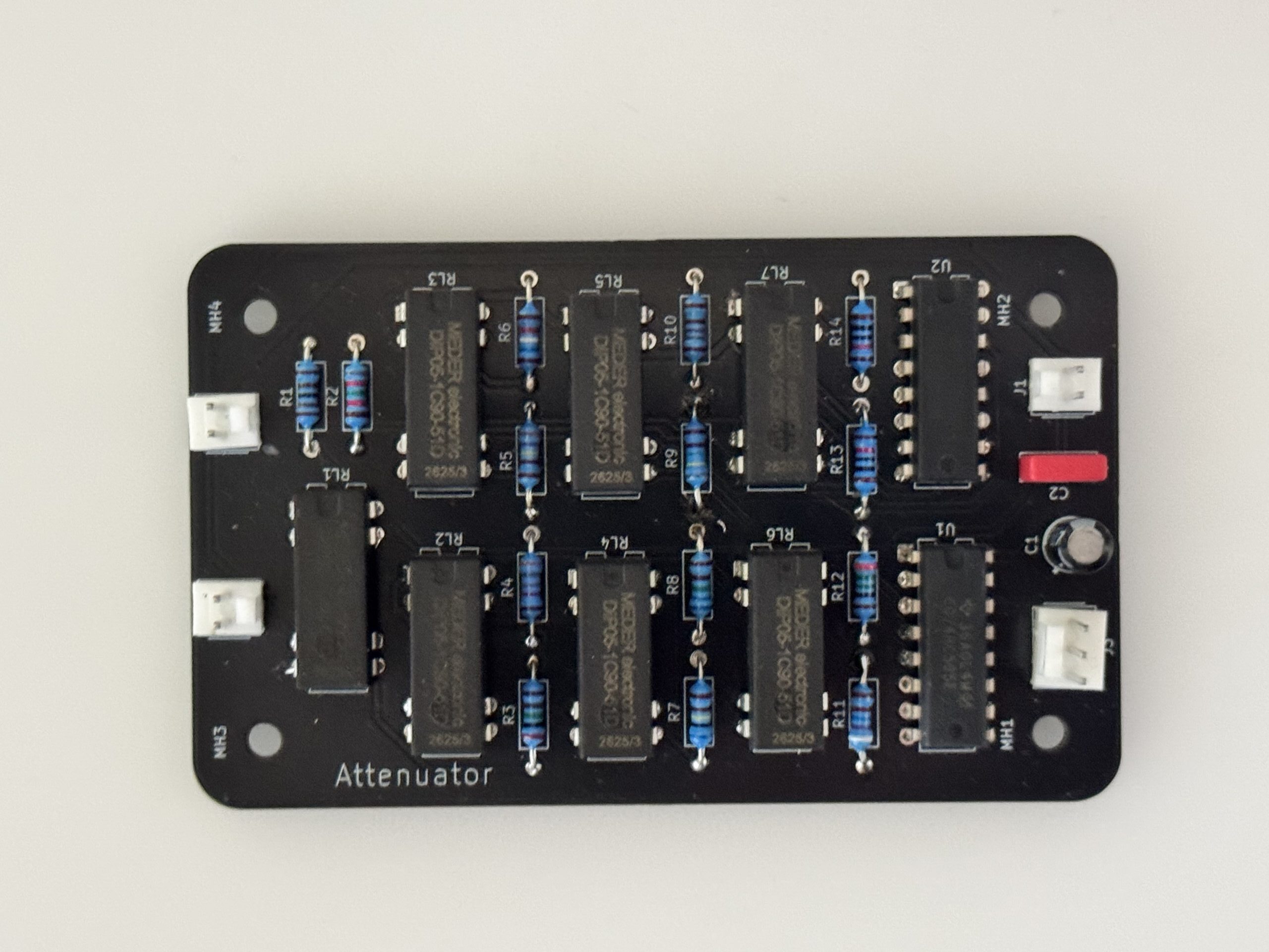
Complete and measured. Built for the Field 25 amplifier, measured across all 64 states and closed on 7 November 2026. This is the record that ships with the board.
Specification at a glance
| Characteristic | Verified value |
|---|---|
| Function | Six-bit binary relay-switched attenuator, constant-impedance L-pad cascade, plus mute relay |
| Range | 0 to 63 dB in 1 dB steps — 64 states |
| Impedance | 10 kΩ, maintained in every state |
| Signal path | Metal-film resistors and sealed reed-relay contacts — no semiconductor, no capacitor, no supply |
| Relays | 7 × Standex-Meder DIP05-1C90-51D, 5 V coil, 1 Form C |
| Control | Three-wire serial (DS, SHCP, STCP); 74HC595 → ULN2003AN; word inverted |
| Accuracy, 0–50 dB | Within 0,196 dB of the ideal curve; fitted 1,0022 / 0,9935 / 0,9853 dB per code |
| Landmark points | code 16 = 15,970 dB · code 32 = 32,022 dB · code 48 = 47,846 dB |
| 51–63 dB | Resolution-limited by the oscilloscope — not established to better than about 1 dB |
| Board | 55,0 × 90,0 mm, 2 layers, 37 nets, 140 plated holes |
| Revision | Design record 1.0 · 7 November 2026 |
What it is
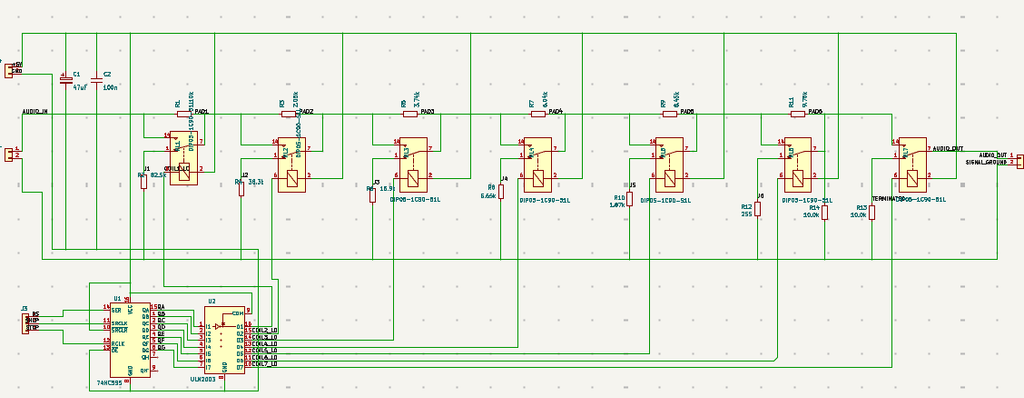
Six constant-impedance L-pads, binary-weighted 1 · 2 · 4 · 8 · 16 · 32 dB, cascaded from the heaviest weight to the lightest. Each pad is one changeover contact: released, the pad is inserted; energised, the series resistor is bypassed and the shunt is left open. Because every pad presents 10 kΩ at its input whatever state it is in, the weights add cleanly — an n-bit word gives n dB, with no correction table.
A seventh relay mutes the output by taking it to ground through 10 kΩ, so the preamplifier never sees an open circuit. A 74HC595 holds all eight bits and transfers them on one edge, and a ULN2003 sinks the coil current. The control word is inverted: relay energised means stage bypassed, so a logical 0 dB is written as 111111.
Schematic
What is not verified
The measurements cover one channel, from 0 to 63 dB, on 7 November 2026: all 64 states present and monotonic, inside 0,2 dB to 50 dB. Below that the oscilloscope’s own floor — 50 µV is a decibel at code 63 — is the limit, so the deepest codes are marked resolution-limited rather than claimed. Channel matching, noise, distortion and long-term contact repeatability have not been measured. The record says so on its first page rather than in a footnote.
Design files
The full engineering design record — 24 pages: design rationale, the attenuation derivation, the switching and control logic, the PCB, the firmware, the development history and the complete 64-state measurement, with the schematic, drawings, BOM, netlist and test data in appendices.
A reproducibility package — GERBER set, KiCad source, netlist, BOM, both firmware files and the measurement table — is available on request.